Description
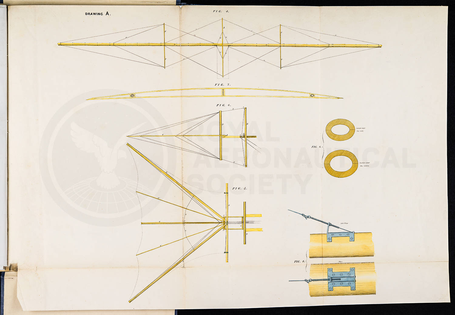
Drawing A, figure 4 shows the side of the frame, figure 5 shows the tail which is used to control the height of the aircraft, figure 6 shows the side of the tail, figure 7 shows the frame bars running from the front to the back of the aircraft and figure 8 shows the cross sections of these bars.
The cross sections would be made of or bamboo to give strenth to the aircraft while keeping it as light as possible.
Figure 9 shows how the rigging is secured to the frame of the steam carriage.
The image is taken from the description, specification and drawings of Mr. Henson's locomotive apparatus for the conveyancing of passangers etc through the air, published by Waterlow and Sons of London and by authority of the patentees.
Date(s)
1843
Collection
WS Henson's 'Aerial Steam Carriage': Specification (1842-1843)
Description
With the exception of Sir George Cayley, the first half of the 19th century witnessed little significant development in aeronautics until William Samuel Henson (1812-1888) published in 1843 his design for an advanced fixed-wing monoplane configuration known as the 'Aerial Steam Carriage'. Incorporating…
Collection Terms
- Person: Henson, William Samuel
- Item Type: Pamphlet

